Almost all of us know that "BAL-UN" is the acronym for "BALanced-UNbalanced", thus we grasp the role of the device that bears the name of "balun" - allow to connect a generator having an unbalanced output (asymmetrical in respect to a reference), as a radiofrequency transmitter with a coaxial transmission line, to a balanced load (symmetrical in respect to the reference), as a dipole antenna or a lot of other kind of antennas, but not a Ground Plane one. The use of a balun let us avoid some drawbacks that would arise if we connected the unbalanced output directly to the balanced input. Actually, a balun is normally bi-directional, i.e. it allows to connect a balanced generator (the same antenna, but now used to receive) to the unbalanced load (the coax connected to the input stage of the receiver), though this function is generally much less promoted in amateur radio literature.
Well, let's come to the point. I've just built a choke bal-un, or current balun (with 1:1 impedance transformation ratio, i.e. it's just a balun, not an impedance adapter). I just want to share the pictures that document my work, I hope that they might be useful to someone else and, why not, that someone will send me his comments and suggestions trough the "Contacts" module of this web site. Honestly speaking, there is nothing new in this article, it just talks about one of the several (thousands? Millions?) realizations of a HF choke. However, I'm sure that nobody would come to this unknown web site by chance, and that most of you are here because you are looking for instructions and pictures to be used as a starting point to homebrew your balun. So, read my article and also some of the other articles that you'll find around on the internet and in the literature. I spent a lot of effort in order to make a tutorial that suits to individuals who don't have specific technical skills, commenting and showing all the mounting operations, including the trivial ones...
Let's build a wide band choke balun for HF, with a good hope that it'll work on 50 MHz band too. We'll realize it with 11 turns of RG-142 coax cable wound on two overlapped toroids, brand Amidon model FT240-43. Why exactly 11 turns? The choice is based on experimental data published by G3TXQ (SK), who gave the figures for 9 turns; in order to compensate a part of the leakage flux due to the much higher stiffness of the RG-142, when compared to the RG-58 used by G3TXQ, which results in less tight turns around the core, I've decided for 11 turns instead of 9. This balun should withstand a power of few kW, but I would not know how to verify that, I can run only 100W .
.
Needed material and equipment:
- A piece of RG-142 coax, let's say about 1,3 meters. The price is between 7 and 11 Euros/m in a shop (I paid it 5 Euros/m at a fair)
- Two Amidon toroids FT240-43; price about 9-10 Euros each
-
One panel mounting female UHF connector (or, if you prefer, panel mounting N type female connector); price starting from 2 Euros
-
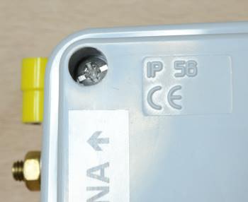
One plastic box (I used a junction box with smooth walls, IP561, dimensions (120x80x50) mm3; price about 2,5 Euros
-
Two brass or stainless steel bolts M3x16 with nuts and washers to be used to fix the coax female connector (I used M3x20 bolts but they are a little too long)
-
Two brass or stainless steel bolts M5x20, each with at least two nuts and washers (to be used as antenna terminals); for all bolts, nuts and washers I spent 2 Euros
-
Adhesive or non-adhesive insulating tape I used a non-adhesive PTFE tape, not to smears the cores with glue; actually, we don't need PTFE, we just need to hold the ferrite cores perfectly stacked and tight one to each other, a thin string like a fishing line could do the job…)
-
Self locking cable ties made of plastic or any insulating material
-
Four cable terminals with 5 mm diameter closed eyelet
-
Two non-insulated cable terminals having 3 mm eyelet diameter; for all the cable terminals I spent 1,5 Euro (at this price, I actually bought many more terminals than needed...)
-
Drill, drill bits (drill bit diameter 16 mm for creating the coax receptacle place, diameter 3 mm for the screw holes of the coax receptacle, diameter 5 mm for the screws that work as terminals for the balanced (antenna) side); for the 16 mm bit I spent about 10 Euros
- Soldering iron, soldering wire
...and all the other stuff that I forgot to list here...
If you already had the tools at home, and the most common materials, the total cost would be around 35 - 38 Euros.
The Amidon FT240-43 toroid cores show like these:


Overlap the two cores and pack them with tight wound adhesive insulating tape, or non-adhesive PTFE tape like me, or whatever thin insulating material you like, so that the cores are accurately stacked without play.
") Wind the RG-142 coax cable. Wind tight in order to avoid magnetic flux leakage, but not so tight as to risk cable damages. Do this operation at an ambient temperature slight above normal, or heat the cable a little to make it warm (I said warm, not hot!), which will help. Consider that the central cable conductor must remain equidistant from the shield conductor (or conductors); if the bend radius is too short, deformation is induced which results in unbalancing. Well, it's not such a worrying problem however, if you could, just avoid it. Furthermore, an excessive deformation of the cable could lead to hairline fracturing of its materials. Some humidity will penetrate these microscopic gaps, that is non-pure water particles. Positive and negative ions dissolved in the water will make it conductive, resulting in isolation loss of the cable both outward and between its own conductors. Later on, because of years of thermal cycling (warm/cold) due to the outdoor environment conditions, the hairline fractures might extend, particularly if you live in an area where temperature often crosses the water freezing point, similarly to the geological phenomenon of rock crushing (frost wedging). All that will worsen the behavior of your balun until a possible failure and its premature end of life. This is one of those things you should not ask me why I know... The properties of the materials composing RG-142 make it much more robust to the phenomena mentioned above than many other coax cables. Last but not least, I don't suggest you to use those newer high electrical performance coax cables that are often advertised as very flexible, because they are very prone to deformation and do not suit well to "maltreatment".
Wind the RG-142 coax cable. Wind tight in order to avoid magnetic flux leakage, but not so tight as to risk cable damages. Do this operation at an ambient temperature slight above normal, or heat the cable a little to make it warm (I said warm, not hot!), which will help. Consider that the central cable conductor must remain equidistant from the shield conductor (or conductors); if the bend radius is too short, deformation is induced which results in unbalancing. Well, it's not such a worrying problem however, if you could, just avoid it. Furthermore, an excessive deformation of the cable could lead to hairline fracturing of its materials. Some humidity will penetrate these microscopic gaps, that is non-pure water particles. Positive and negative ions dissolved in the water will make it conductive, resulting in isolation loss of the cable both outward and between its own conductors. Later on, because of years of thermal cycling (warm/cold) due to the outdoor environment conditions, the hairline fractures might extend, particularly if you live in an area where temperature often crosses the water freezing point, similarly to the geological phenomenon of rock crushing (frost wedging). All that will worsen the behavior of your balun until a possible failure and its premature end of life. This is one of those things you should not ask me why I know... The properties of the materials composing RG-142 make it much more robust to the phenomena mentioned above than many other coax cables. Last but not least, I don't suggest you to use those newer high electrical performance coax cables that are often advertised as very flexible, because they are very prone to deformation and do not suit well to "maltreatment".
(Once the 5 turns are wound on one side of the core, you pass the cable through the hole of the core and then you wind the remaining 5 turns on the other side. At this point, the unborn balun looks more or less like this. Observe that the PTFE tape is now somehow worn out, what to say, RG-142 is an ugly beast to tame!
 Case preparation or, in other words, drilling:
In order to make the assembly easy, the coax connector will be placed inside the box, therefore you have to drill a hole having the same diameter as the maximum diameter of the connector threaded part that will come out from the box (in my case, 16 mm diameter). You can measure the diameter with a caliper. The two holes for the screws of the connector flange in my case have a diameter of 3 mm, you could stick some way the connector to the box and drill through the screw slots of the connector. As I said, two screws are enough. The connector flange bust be positioned with the screw slots one on the right and the other on the left, on the same horizontal axis of the big hole in the middle.
On the opposite side of the plastic box, we practice two holes for the antenna terminals with a 5 mm diameter drill bit. If you prefer, you can make these holes on the back side of the box, not quite a comfortable place, though. Obviously, placing the terminals on the cover is not convenient. I would not place the terminal holes on the longest sides of the box, unless a vertical path for the antenna wires were needed, like in the case of the connection to stiff dipoles (e.g. a Yagi-Uda antenna radiator). I will use horizontal or sub-horizontal dipoles made with electrical wire, thus the terminals position like in the pictures here around are ok with me, but it's your choice.
If you are thinking to apply some links to the box, this is the right moment to drill the holes that you need. Remember that water must be kept out of the box, so all the holes, in the end, must result plugged by something, leaving no room for water to penetrate. Actually, here we come to a tricky consideration. As a matter of fact, we will not be able to seal the case under vacuum or in controlled inert atmosphere, so I couldn't say if some drain holes for condensed water (in the bottom side) and, may be, a hole to let the steam out (in the top side, but not in the same wall of the antenna terminals), were better than perfectly sealing the box against humidity (which, however, we could not avoid, unless we had very expensive equipment). In the end of the day, I just ignored the issue, I will judge in a few years from now. I say it again: in any case you must not drill such big holes, or holes in such a position, to let water into the box!
Now it's a matter of trimming the cable, strip the sheath on one end and connect the coil to the coax connector. Obviously, first you strip the external sheath, the screen strands must be untangled using your fingers and a little rod, like a screw driver to lose the mesh and separate the thin wires. Then, we collect these thin wires in two bundles and, twisting separately each bundle, we obtain two braids. Each braid must be terminated soldering a tinned copper "flake" with 3 mm diameter slot ("flake", I don't know how to call it in English, it is a light non-isolated wire terminal lug). We Always trim the lengths so that the device could be comfortably be housed in its box). Then, we strip the inner conductor removing its dielectric sheath up to few millimeters distance from the point where the screen branches in two. You know that screen and central conductor must never touch each other and must stay always well separated. The central conductor of RG-142 can be soldered directly into the central receptacle of the connector.
When, later on, we fix the connector to the case, each M3 screw is inserted from the outside of the box, possibly with a washer between head of the screw and plastic wall (I didn't have it); inside, we pass the screw through the slot of the connector flange, then into the "copper flake" slot and we tighten a nut. If you want, you can put another washer between nut and copper flake, I wouldn't do that though. Do not put the washer between copper flake and flange! If you preferred, you can also solder the two braids directly on the flange, without using the copper flakes. In such a case, the connection will be improved from the electrical point of view, but a little difficult to manage.
Now, we strip the opposite end of the cable, more or less as we just did before, but this time we trim the wires to connect to the antenna terminals. Here, with the screen strands we make just one braid that we terminate with a terminal lug (slot diameter 5 mm, without insulator) both crimping and soldering. Same termination for the inner conductor.
You must clean everything well, in particular were you made solderings, removing the flux and anything else. You can use denatured iso-propyl alcohol and paper towels. Later, you can rinse first with clean water from the tap, and then with a little quantity of distilled water, so to clean also the impurities of the drinkable water. I don't know if ultra-sounds cleaning suite well to ferrite. I would say it does not, so I did not use it. Everything must be definitely dry before going on with the assembly.
If you want to mount links to the box, do it now. At the moment, I don't need them.
We put the device into the case, and we connect the coax to the connector as just said. On the antenna side, instead, insert M5 screws from inside the box outward. Ring the screw with the terminal lug first, then the washer, then insert the screw in the slot on the plastic box wall, then put another washer outside, a nut and tighten. Here, you will put another terminal lug (always with 5 mm slot, but do not remove the insulator, this time) which you have already connected to one of the antenna wings. Finally, put the last nut and tighten.
Close the box with its own cover and tighten its tapping screws applying a moderate torque (0,8 N*m for my box, anyway, if you can't measure the applied torque, it'll be ok, just don't tighten too much in order not to damage the plastic box).
With a tester, verify that the connector screen is connected to one antenna terminal, that the inner contact is connected to the other antenna terminal and that the isolation resistance between the two conductors tends toward infinity. If you measured a resistance of some megaohms, it's not good! In that case, double check your assembly looking for bare conductors too close to each other, and wash again everything as already explained.
I have the impression that your balun is ready. Make your measurement or test your balun on the field.
OK, as I said, I put a lot of effort to share the instructions well enough also for people with low experience but, if something goes wrong, don't complain with me... 
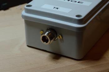
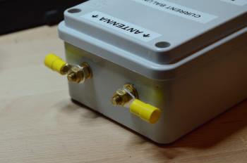
Balun: N connector (an UHF, BNC or whatever connector will be just fine); antenna terminals with lugs; case marking.
Note:
- Meaning of code IP56(EN 60529): case is protected against dust, against contact and against powerful water jets.
Source: ik1hge.com, realized and written by ik1hge; based on measurements performed and published by G3TXQ.

This work is licensed under a Creative Commons Attribution-NonCommercial-ShareAlike 4.0 International License. Author: ik1hge
")
")