I like electronics, telecommunications, photography, playing various instruments, programming... There are a couple of recent projects that I'd like to show to you. Let's begin with a 432 Mhz Quagi antenna.
I tried N6NB's project but it didn't work well. Actually, there were some differences from the original project: for the Driven Element and the reflector, I used 1.8mm solid copper wire (the one for coils or transformers) because, at least in Italy, the old insulated #12 TW solid copper wire is too hard to be found. Furthermore, the Directors diameter was 4mm instead of 3mm. Probably these differences resulted in unacceptable Standing Wave Ratio, as you can see here below:
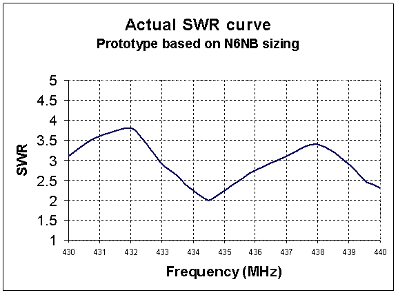
Fig. 1 Experimental SWR curve obtained with N6NB's design (materials as specified in the text above)
Someone suggested me to optimize the antenna through NEC2, and... here you are the first results.
This Quagi is optimized for
432.2Mhz operation, however it works well in a quite wide range of frequency. All following data are obtained through 4NEC2D v. 5.3.2 by Arie.
The protype behaves better than I expected, but it seems that the Driven Element requires a little adjustement due to mounting approximations and to the coating of the copper wire. In my prototype, the Driven Element required to be shortened of about 3mm.
I suggest to:
1) Build the antenna by using the design data here below
2) Run a SWR curve
3) Adjust the DE length. An estimation of the new length is: DE(new) = DE(old) * fSWRmin/432.2
where fSWRmin is the new frequency in MHz of minimum SWR. However the actual length depends on your peculiar construction, thus take it easy and don't cut too much!
I put some experimental results and the pictures of the prototype at the bottom of this page. I only regret that I did not record the SWR curves taken when the Driven Element was 741mm and 738mm long, however you can see that with 735mm the minimum SWR is @ 434.5MHz. You can also see the comparison to a simulated antenna with 735mm DE which includes loss due to non-ideal material.
Have fun!
|
Parameter |
Value |
Unit (Conditions) |
|
Frequency |
432.2 |
MHz |
|
Gain |
13.77 |
dBi in free space |
|
SWR |
1:1.03 |
(432.2 MHz) |
|
SWR (min) |
1.01 |
(432 MHz) |
|
Bandwidth |
430-434 |
MHz (SWR<1.4:1) |
|
Take off angle |
1.8 |
Degrees above a good ground (antenna height, about 8 wavelengths) |
Table 1 Antenna performance (MOM simulation)
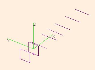
Fig. 2 Structure of the Quagi antenna
Stupid proof note added on 2018-01-17: The "Length" of the Driven Element (DE) and of the Reflector (RE) is the total perimeter of the square that must be formed by the wire! This means that each side of the element is 1/4 (one fourth) of the length reported in the following table. The Directors (D1, D2, …, D6) are just straight pieces of aluminum, thus there is no dubt about what is their length. Believe me or not,in these years I have received several hundred questions and complaints by people who made the DE and RE four times bigger than the project dimensions. Yes, it was about time to write this note…
|
Copper wire diameter for the square elements |
0.0018 |
Aluminum directors diameter: |
0.004 |
Boom (wood): 1.50 |
|
Element |
Length |
Position |
Spacing |
|
|
RE |
0.76215 |
-0.22904 |
DE-RE |
0.22904 |
|
DE |
0.7413 |
0 |
DE-DE |
0 |
|
D1 |
0.29365 |
0.13093 |
DE-D1 |
0.13093 |
|
D2 |
0.29213 |
0.40783 |
D1-D2 |
0.2769 |
|
D3 |
0.28042 |
0.57751 |
D2-D3 |
0.16968 |
|
D4 |
0.28618 |
0.7632 |
D3-D4 |
0.18569 |
|
D5 |
0.28384 |
1.0228 |
D4-D5 |
0.2596 |
|
D6 |
0.27414 |
1.2687 |
D5-D6 |
0.2459 |
Tab. 2 Design details (meters)
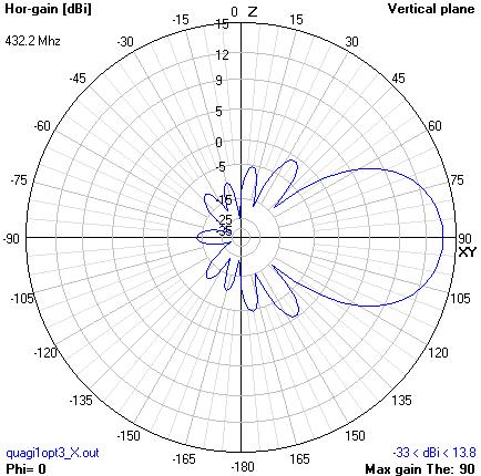
Fig. 3 Vertical (Elevation) pattern in free space
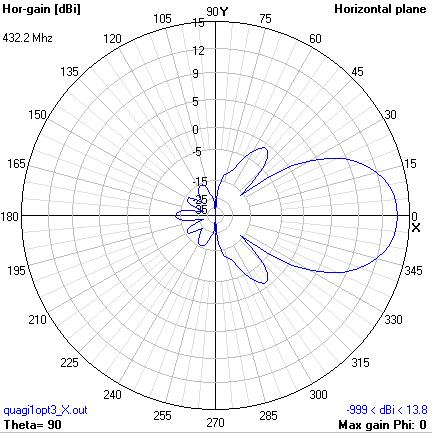
Fig. 4 Horizontal radiation pattern in free space (horizontal component)
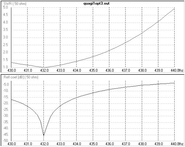
Fig. 5 SWR and reflecttion coefficient charts
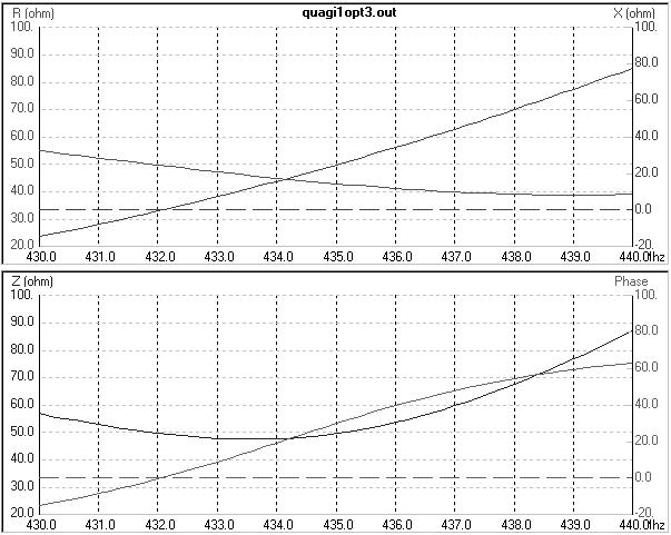
Fig. 6 Impedance charts: Resistance,Reactance (top) and Impedance,Phase (bottom)
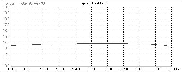
Fig. 7 Total Gain vs. Frequency
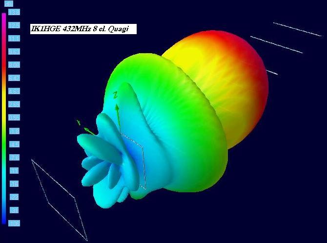
Fig. 8 IK1HGE 432MHz 8el Quagi - 3D horizontal gain plot
The construction details are described in N6NB's article, in the ARRL Antenna Handbook and in many places on the net. Just search for "Quagi".
Here below, find some suggestions and some pictures of my prototype.
-
Use some kind of coating to protect the boom from humidity and sun.
-
To hold each square, I used two strips of FR4, that is the normal substrate for Printed Circuit Boards (completely remove the copper foils first!)
-
The Driven Element is fed trough a female N connector and a short piece of RG213. Protect the connection points to the square. To make the conection more flexible, I suggest to use a thinner coax instead (like the RG58). You can then use the RG213 for the longer line connecting the RTX to the antenna.
-
After the directors are perfectly aligned, you can fix them with a drop of glue.
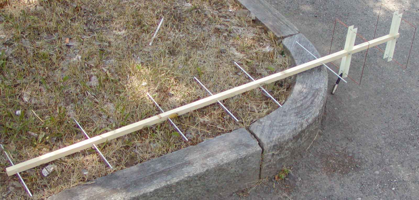
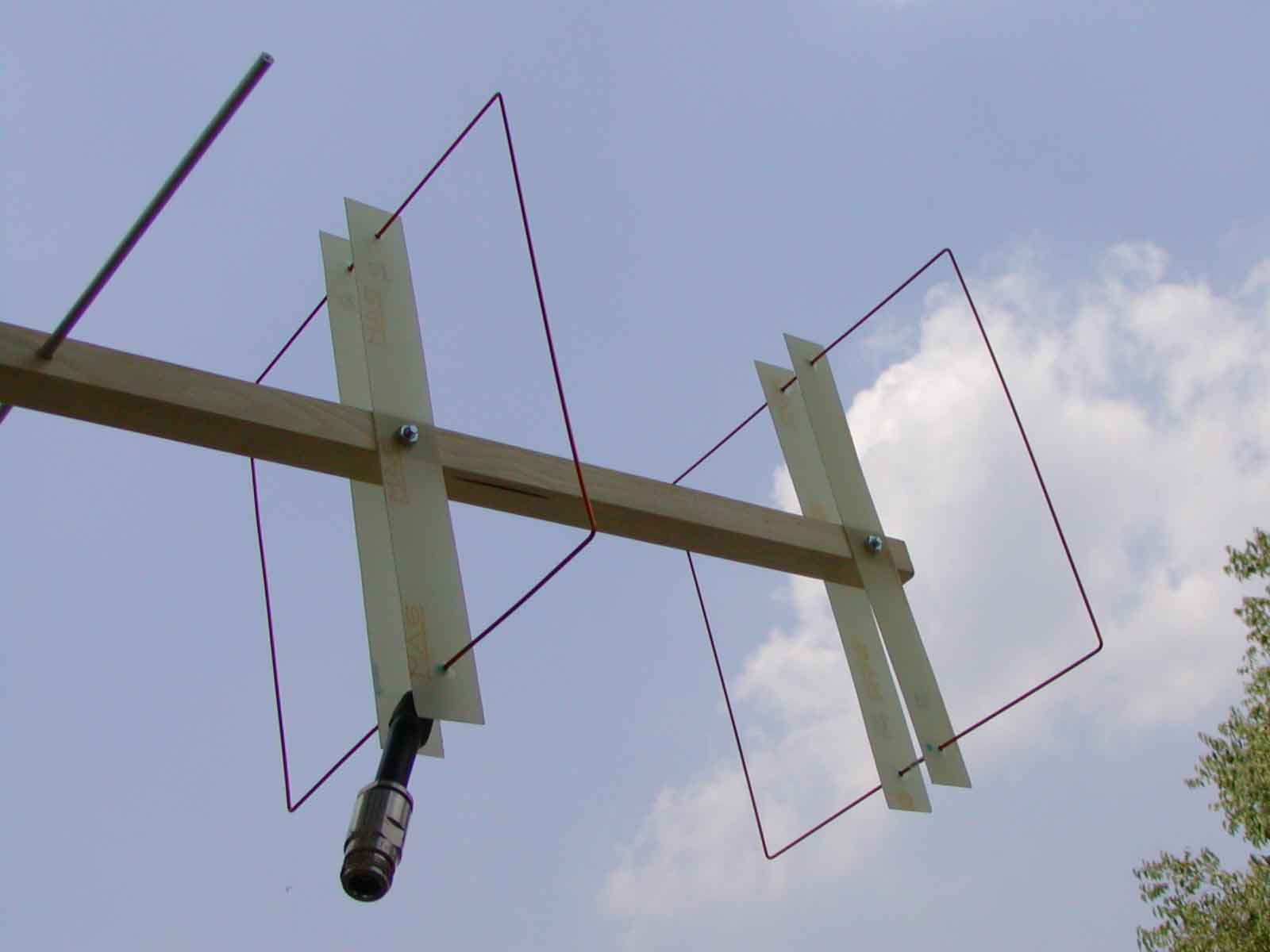
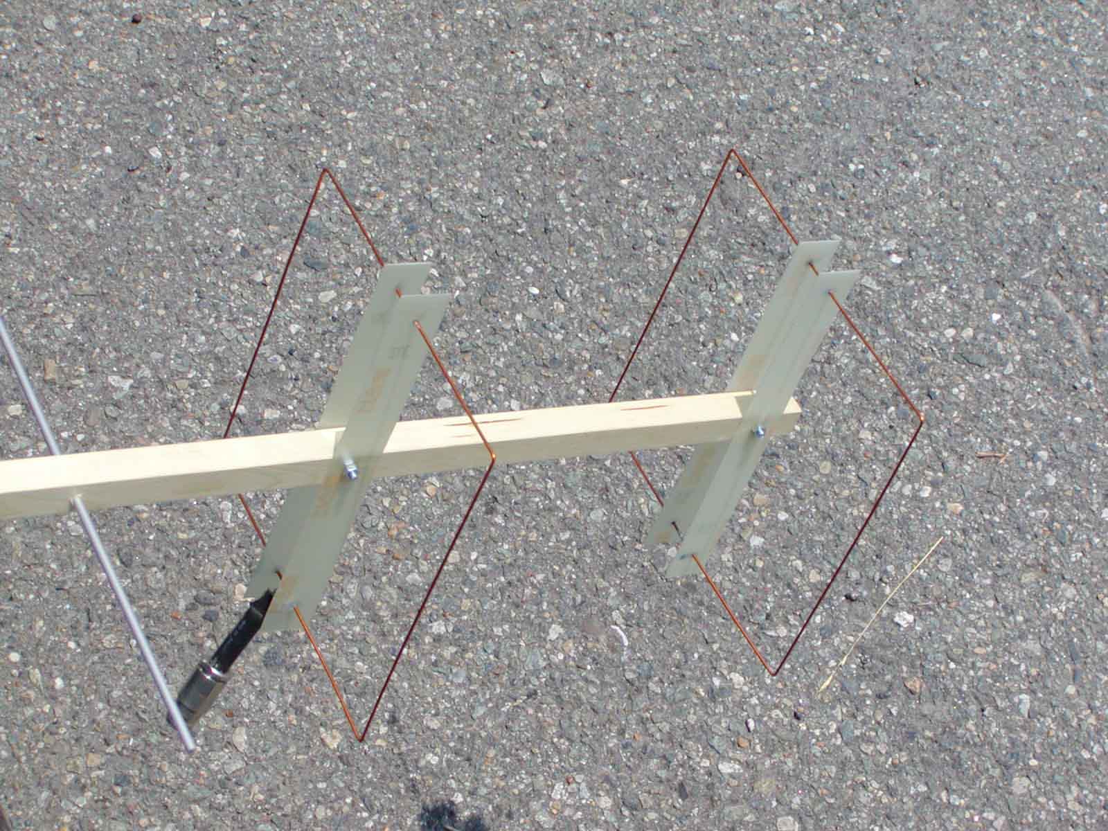

Fig. 9 IK1HGE 432MHz 8el Quagi - Prototype construction details
Find more pictures here: Quagi pictures
I appreciate your comments about this project. For further information or to give me some feedback about your experimental version of this design, e-mail me:
Note added on 2019-01-17: After so many years, prototypes of my version of Quagy antenna have been made by several homebrewers. Furthermore, my project criteria have been copied by other people who scaled my design to different working frequencies. Despite I am frequently contacted by radio amateurs, engineers, students and professors who ask ne details for their realizations, I've never received a picture showing a prototype made by someone else. I'd love to get some pictures of your realization, and publish them online. Please, send me photos!

This work is licensed under a Creative Commons Attribution-NonCommercial-ShareAlike 4.0 International License. Author: ik1hge


