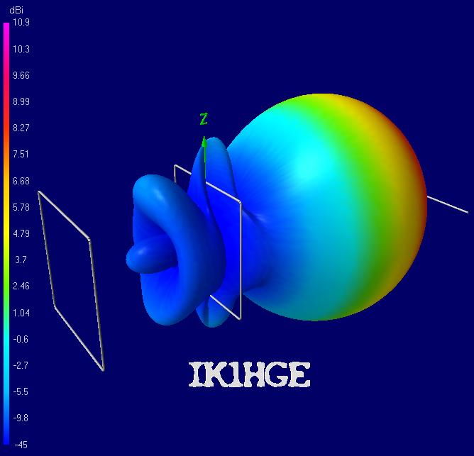
 Would you like to build a simple antenna for 70 MHz band? I sized "on the fly" this 4 elements Quagi for 4 meter band, but I did not make any prototypes, yet; anybody wants to make one?
Use aluminum pipe, diameter 10mm x 1mm thickness. You find it in DIY shops in 2 meters long pieces, or in non-ferrous metals storesin 4 meters long pieces (yeah but, how are you then going to carry it to your home?) so you'll need to make at least one or two joints.
In order to make sharp corners for the loop elements, because bending the aluminum pipe with small curvature is not that easy, I kept into account a curvature radius of 30mm (three times the tube diameter). However, if you can get even a sharper corner, that's good for your antenna!
The antenna boom must be made of wood or other non-conductive material (the boom is not shown in the pictures because, beeing insulating, it's not needed in the simulation model).
Feed your antenna in the middle of an horizzontal side of the "Driven Element" (the one
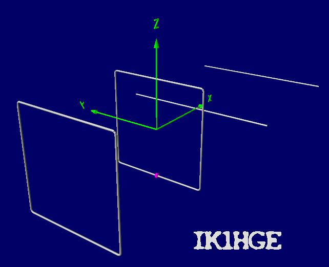 named "DE"), by creating a gap in the loop, about 1cm wide or less. I would crimp a wire terminal to the hot conductor, and one to the shield of the 50 ohm coax cable, and then I would screw the wire terminals onto the aluminum terminals of the loop. If you know how to make better reliable connections, let me know...
This Quagi antenna is designed for resonance on 70.2MHz with purely ohmic impedence of 50 ohm "all inculsive" (that is, including radiation resitance and the small loss in the metal). You might use it without any balun, anyway I suggest to make at least a few loops with the coax cable as close as possible to the antenna feed point., or to insert a 1:1 balun with low loss on 70 MHz.
Try to be as precise as you can. Refer to the several tricks and tips about Quagi antenna homebrewing that you can easily find on the net, tipically for VHF and UHF ham bands.
If you make this antenna, feel free to contact me because I would be happy help and assist you. Do it especially in case you need to use different materials than those that I considered, if the Al tube diameter is differnet than 10mm, or if you want to make fillets with a tub of different diameter.
All data and pictures shown in this page are computed with NEC2 by using 4nec2 di Arie Voors.
Enjoy antenna homebrewing!
IK1HGE (also "misknown" as AI4YG)
|
Parameter |
Value |
Unit (Conditions) |
|
Frequency |
70.2 |
MHz |
|
Gain |
10.9 |
dBi in the free space |
|
SWR 1: |
1.01 |
(70.2 MHz) |
|
SWR (min) 1: |
1.01 |
(70.2 MHz) |
|
Bandwidth |
69.8 - 70.55 |
MHz (SWR less than 1.4) |
|
Tale off angle |
10 |
Degrees above a good ground (Height 5.5 meters, as expected with a 6 meters mast; for better performance, place it at least at 8.5m above ground) |
|
Aluminum tube diameter for building the square loops: |
0.01 |
Aluminum directors diameter |
0.01 |
Boom length (wood) 3.92 |
|
Element |
Length |
Position |
Spacing |
|
|
RE |
4.5983 |
-1.3077 |
DE-RE |
1.3077 |
|
DE |
4.5105 |
0 |
DE-DE |
0 |
|
D1 |
1.8605 |
0.8004 |
DE-D1 |
0.8004 |
|
D2 |
1.8400 |
2.5450 |
D1-D2 |
1.7446 |
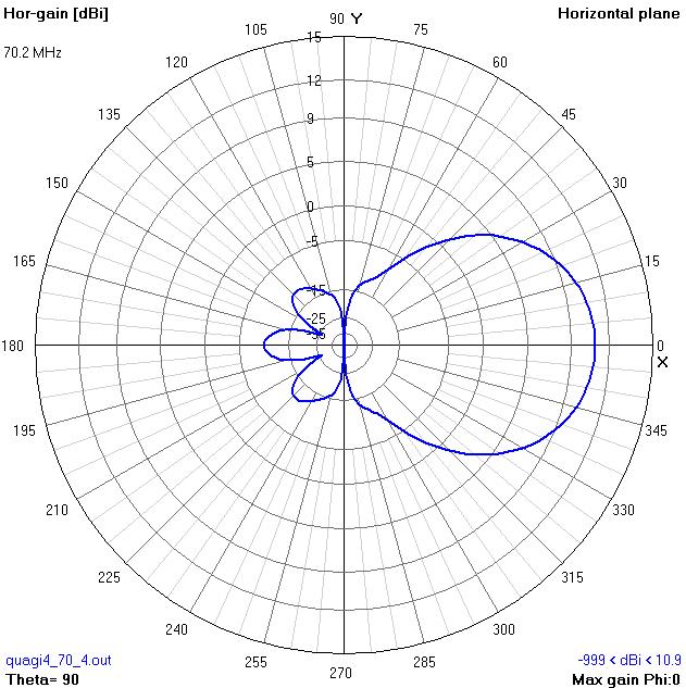
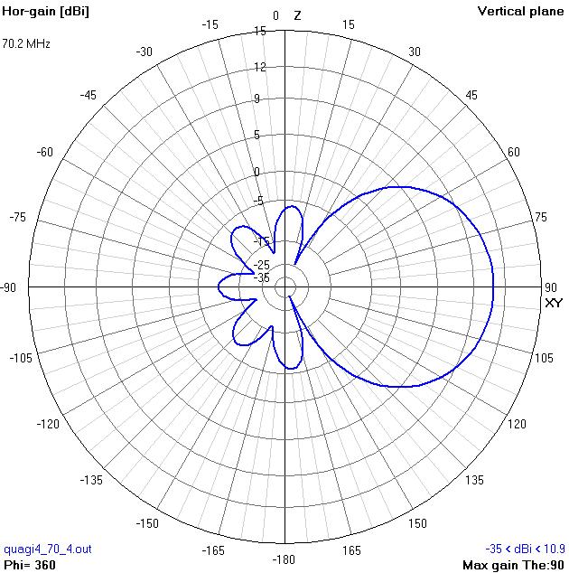
At the time when I dimensioned this antenna, the 4 meter band in Italy is from 70.1 to 70.3 MHz thus, as you can see from the SWR and impedence charts,the antenna is centered on 70.2MHz and it has an acceptable SWR over a more than enough bandwidth. THe simulations are normally affected by a relative error of 1%. In my previous project I measured an error of 0.4%, which also includes the tolerances of the human execution. This means that, in your prototype, you must be able and ready to sligthly shorten or lengthen at least the Driven element... You might make a telescopic junction somewhere, that is 20cm long tube, diameter about 8mm, inserted into the 10mm tube and tightened with a couple of self tapping screws. To calibrate the antenna, slide the tubes one into the other and then tighten the screws.
.
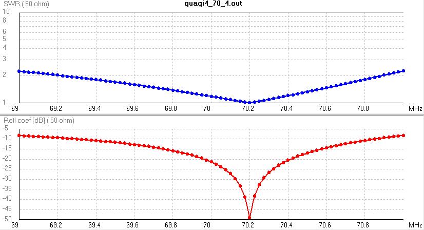
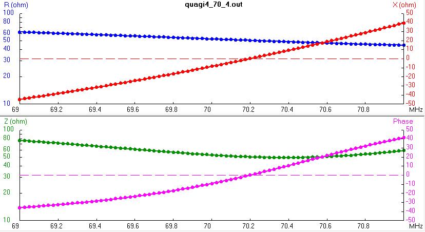
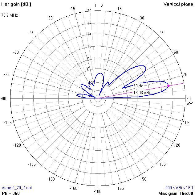
The pictures here above refer to the antenna palced in the free space. In the following diagram, instead, we imagine to place the antenna on a 6 meters mast, so that the antenna height will be about 5.5 meters, measured from ground to the boom (horizontal axis of the antenna).

This work is licensed under a Creative Commons Attribution-NonCommercial-ShareAlike 4.0 International License. Author: ik1hge


